|
I
know...! I know…! How did we get to this point so fast in the
construction process of the VSC “North Star” Field Tripod
prototype! Well, I must say that I did not capture many photographs
when I was building the unit, because I was in a hurry to get the job
done before Gary Barabino left to go back to Louisiana. But, I will
try to put the basics into words. In any case, I believe the average
woodworking hobbyist would not have a problem understanding the layout
from the photos provided. Additionally, you could check out the design
diagrams for an animated interpretation of the project.
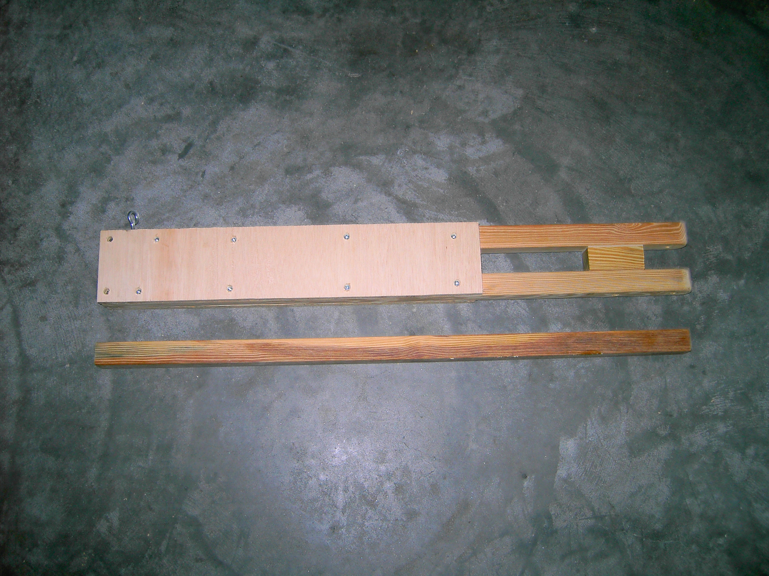
As
you can see in the photo above of one of the three completed legs,
each leg is basically comprised of three 2x2 hard pine stakes, two
panels of plywood, a spacer made from a 3” inch section of 2x2 hard
pine with a matching piece of 1/8” inch craft plywood and hardware.
In
constructing the legs for Gary’s tripod, I did not have to cut the
48” inch stakes by much. Gary is a rather tall guy, and the height
worked for him. Of course, for us stubbier folks, the field tripod can
be customized to you personal height requirements.
The two 2x2 hard
pine stakes used as the “main leg supports” were rounded at one
end with holes drilled for attachment to the Pan-Head. Then the bottom
inside edge of one of the “main leg supports” was notched at a 45º
angle to allow the pivot joint of a strap to lay flat for use as the height adjustment locking system. The lower
inside of the leg was fitted with a T-Nut for insertion of an eyebolt
(more on this later). Then, the two “main leg supports”
were spaced apart using a 3” inch 2x2 spacer block, along with a
1/8” thick piece of craft plywood to increase the separation to
allow the “adjustable center leg” to freely move up and down
during height adjustment of the tripod. The side of the 2x2
“adjustable center leg” that face the back faceplate of the tripod
leg, between 1/32” to 1/16” inch of material was removed with
several passes of the piece against a spinning cylinder on a drill press. This was done so
that the “adjustable center leg” of the tripod could fit easily
between the front and back faceplates, allowing the tripod to be
raised and lowered freely. Then, everything is sandwiched together
between two ¾” inch plywood panels, which formed the front and back
faceplates. Woodscrews, and in conjunction with waterproof Polyurethane
adhesive were used to hold the faceplates to the “main leg
supports” together.
|
|