| North
Star Tripod - Construction Overview - Tripod Leg (Top) |
|||
|
| North
Star Tripod - Construction Overview - Tripod Leg (Top) |
|||
|
|
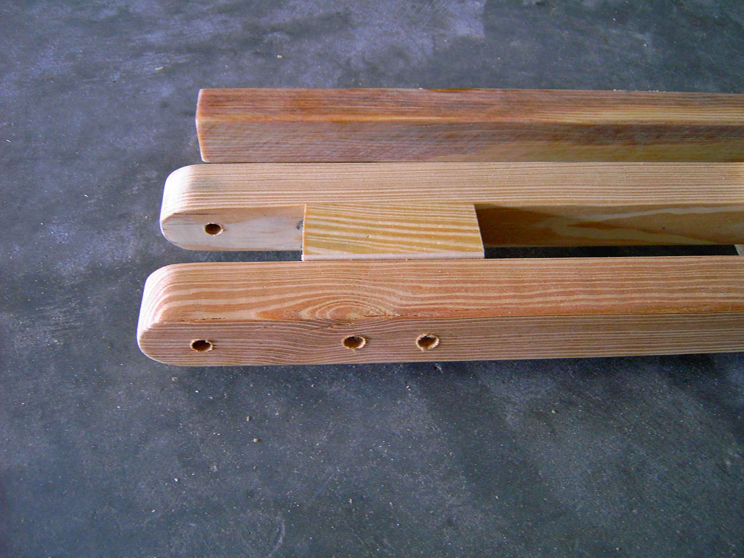
The
above image is a close up of the top portion of one of the completed
legs, along with its “adjustable center leg” at the top of the
photo. As you can see, a hole was drilled through both of the “main
leg supports”, about 1 ˝” inches below the curve at the top of
the leg to accommodate a 6” inch long by 5/16” inch carriage bolt
for marrying to the Pan-Head. To space the two “main leg
supports”, a 3” inch section of 2x2 hard pine stake along with a
1/8” inch craft plywood
spacer (to increase the opening for the “adjustable center leg”)
was used. To pull it all together, two 3” inch long drywall or deck
screws are used on one side, and one on the other. The spacer serves
three purposes: 1.)
Separates the “main leg supports” to allow the “adjustable
center leg” to provide adequate clearance to slide freely between
them. 2.)
Acts as a height stop when the legs are retracted. 3.)
Provides additional strength by reducing twisting and flexure of the
legs at the Pan-Head connection, offering similar attributes found
with a Gibraltar tripod.
|
|