|
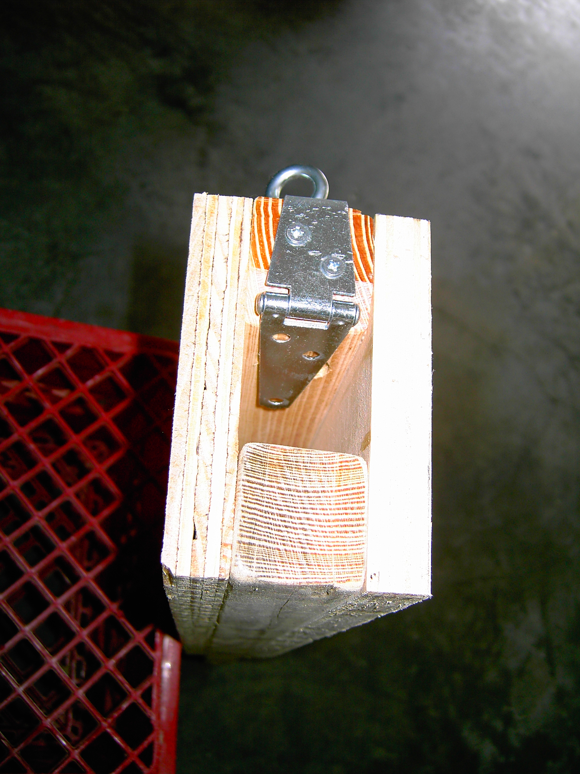
Here
is the bottom end of one of the VSC “North Star” tripod legs with
the “adjustable center leg” removed to reveal its height
adjustment locking mechanism. The locking mechanism consists of a 3”
Strap Hinge, three small woodscrews, a T-Nut, and an eyebolt per leg. Simple in
design, yet it works quite effectively when holding the “adjustable
center leg” when it is extended.
The way the height
locking mechanism works, is a 1/4x20 T-Nut (hidden behind the strap
hinge) is attached to the inside wall of one of the 2x2 “main
leg supports”, for which a 5/16” inch hole was drilled about 2”
inches up from the bottom of it. A 1/4x20 2” inch long eyebolt is
then screwed into the hole opposite the T-Nut. At the end of the same
“main leg support” member, a bevel has been cut at a 45 degree
angle to accommodate the protruding pin of the pivot joint of a 3”
strap hinge.
One half of the strap hinge is inserted up the interior and is
positioned in front of the T-Nut inside the opening. It is designed to
push against the “adjustable center leg” by tightening the
eyebolt. The other half of the strap hinge is then attached to the
bottom end of the same “main leg support” with two small
woodscrews. Then the remaining overhang of the strap hinge is bent (see
note below) around the bottom edge of the “main leg support”.
Next, another small woodscrew is used to secure the tip of the bent
overhang to the outside of the main leg support, just below the
eyebolt entry hole. A better view of this can be seen on the next
page.
|
|